Pressure management and loss reduction

Set pressure to match demand with Metirius Limit

Flow control valves (FCV) and pressure control points (PCP) work together: enough pressure is maintained for the end user, unnecessarily high pressure is reduced when demand falls, and water losses decrease. In suitable applications, the potential water saving is around 25%.
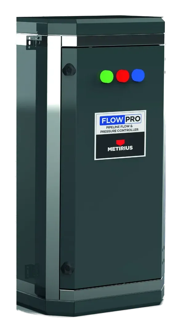
Wall-mounted Metirius flow and pressure control panel with coloured status lights

Two panels, two tasks

The decision algorithm runs on the control unit in the field. Each component takes on a different task in the control loop.

ComponentLocationRole in control
Metirius PCPThe point representing the zone’s critical end userMonitors pressure, makes the pressure decision based on end-user needs and sends it to the FCV
Metirius FCVThe point that manages water inflow to the zoneChanges the position of the actuated valve; sets the flow into the zone to meet the pressure requirement of the PCP

How the system works

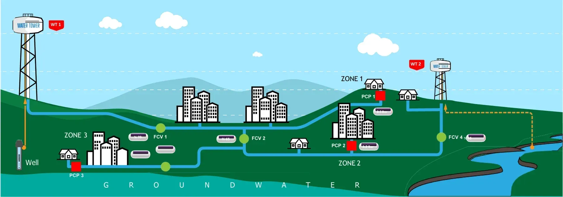
The system uses Metirius PCP (pressure control point) and FCV (flow control valve) devices. Each FCV system is designed to manage one zone. When a zone has to be supplied from more than one water source, two or more FCVs are used and these devices are operated simultaneously.

In the example in the diagram, Zone 2 is supplied from two different sources. The required pressure at PCP 2 is achieved through flow control in the FCV 2 and FCV 4 chambers. These chambers communicate through the automation system. One FCV unit operates as the primary unit and the other as the secondary unit. The primary unit passes the control information to the secondary unit.

Three-zone network diagram: water towers, a well, the FCV 1, FCV 2 and FCV 4 valve chambers and the PCP 1, PCP 2 and PCP 3 pressure points

The decision at the PCP, the action at the FCV

The pressure decision is made at the point next to the end user, and the valve position follows it. The decision algorithm runs on the control unit in the field; Predixi WIS is the environment for monitoring and remote management.

  1. 01

    The PCP measures and decides

    Taking the end user in the zone as the reference, the pressure needed to avoid water shortages is determined and sent to the FCV chamber. Pressure decisions are made by the PCP.

  2. 02

    The FCV adjusts the flow

    The actuated valve controls the flow by adjusting its percentage open according to the information from the points.

  3. 03

    The network responds

    The PCP takes the new pressure reading and the control loop continues; when demand falls, unnecessarily high pressure is reduced.

FCV chamber

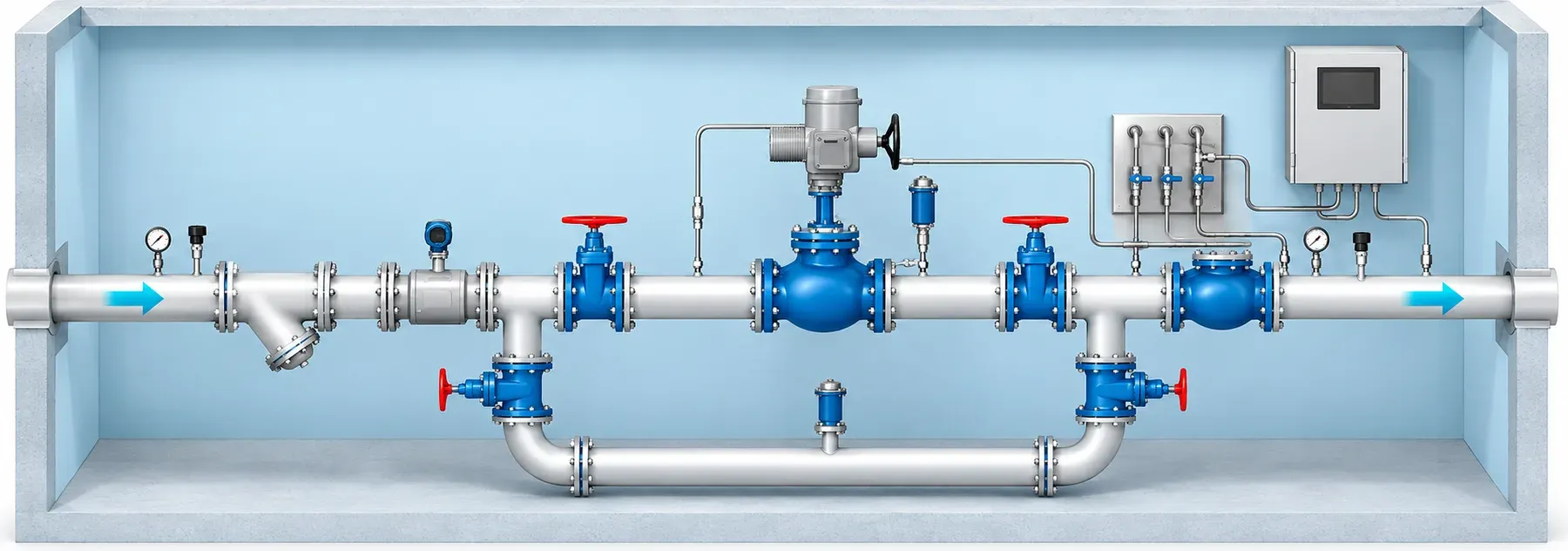
FCV chambers are installed at the required points and contain the sensors and control systems needed for efficient operation. They provide more detailed, real-time control than pressure control valves.

The FCV chambers and PCP points communicate with each other. The actuated valves control the flow by adjusting their percentage open according to the information from the points. Pressure decisions are made by the PCP. In drinking-water systems, pH, conductivity, chlorine and turbidity are also measured.

Drawing of an FCV chamber: actuated valve, meter, pressure gauges and field control panel

PCP chamber

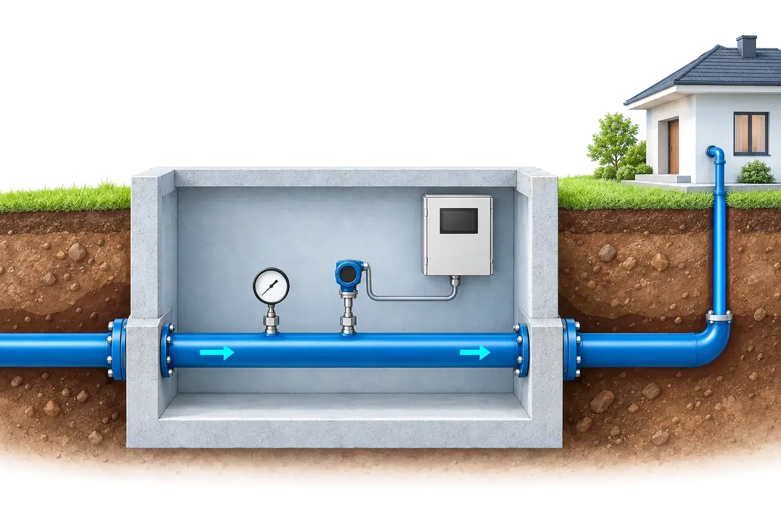
PCP chambers, installed at the required points, contain a Metirius PCP panel and a pressure gauge. Taking the end user in the zone as the reference, the pressure that prevents water shortages is sent to the FCV chamber.

Cross-section of a PCP chamber: pressure gauge on the pipe, pressure sensor and the Metirius PCP panel on the wall

Pressure that matches demand, not constant pressure

  • Scheduled operation

    The flow through the FCV points can be set according to the leakage rate in the mains, the cost of the water and the capacity of the sources. Losses can be reduced by drawing less water through mains with higher leakage. Taking source costs into account, more water can be drawn from the low-cost source and less from the high-cost source. Reducing leakage and using low-cost sources lowers system costs.

  • Daily water consumption: current operation

    A look at a city’s daily water demand shows that consumption can stay high even in the hours when use approaches zero. In a conventional pressure control valve system, the pressure the end user needs at peak use is held constant without regard to actual demand. As a result, water losses stay high even when no water is being used.

  • Daily water consumption: target operation

    At times of peak water consumption, the system sets the pressure so that the end user does not run short of water. When demand falls, the pressure is lowered and water losses are reduced. You can define on which days, in which time windows, in which zone and at what pressure the system operates. The required pressure is thus delivered in real time through indirect flow control rather than a conventional pressure control valve.

  • Decisions in the field, settings from the centre

    The decision algorithm runs on the control unit in the field. Predixi WIS is where you monitor the readings and update parameters and scenarios remotely.

The installation is chosen to suit the zone’s control needs

Monitoring and control are implemented together or separately, depending on the feasibility study.

InstallationPurpose
Monitoring with PCPContinuous visibility of the pressure at the critical point and the current state of the network
Control with FCVManaging the flow through the supply main according to defined operating needs
FCV and PCPAdjusting the flow in coordination, with end-user pressure as the reference
Multiple FCVs and PCPsSupplying the same zone simultaneously from different sources, according to a common pressure requirement

A potential, not a result

potential water saving in suitable applications
~25%
potential additional energy saving from reduced pumping
~15%

These values are potentials; they depend on the structure of the network, the quality of measurement and the scope of the application. The indirect reduction in CO₂ emissions depends on how much less electricity is needed and on how that electricity is generated.

A closer look

  • PCP chamber beneath the city: ladder, pipeline and the Metirius PCP panel on the wall
  • Water valve and pipe connections in a valve chamber in the field
  • Gate valve and meter on a red pipe in a corner chamber
  • Cross-section drawing of a leak in a pressurised pipe beneath houses

Designed around your operation.

Let’s plan the measurement, feasibility and control structure of your network together.